Intro
Since I am a fan of DYI and love gadgets(and IoT), I started to play with a Raspberry Pi and ESP8266 for a while. I had some failing ideas like automating my curtains, after long plans and setup, I abandoned the idea because I couldn’t see a way to make it look nice with the Raspberry Pi board. But now I finally managed to wrap up something that I use and would like to share with others.
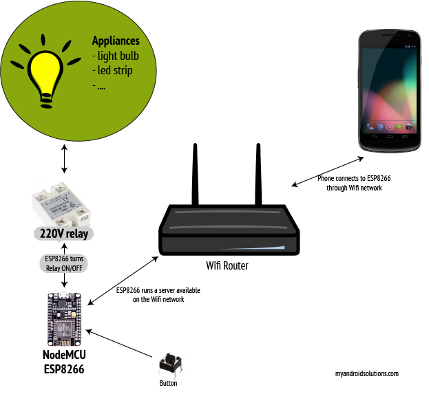
It is about automating my kitchen led band by adding the ability to switch it off/on using and Android phone and a physical button(because you don’t have the phone on you in the house always :P ).
The first IoT “Thing”
I would like to call this setup a “thing” from the IoT (Internet of Things) because I would like to work more on it and finally make it behave just like a real IoT thing.
At this moment we can name it “Smart switch” because it can connect to a Wifi router and switch a relay ON and OFF, and it also has the fancy button. I hope in the near future to smarten it more and more. Currently as I said, with the relay, I am switching my kitchen’s led band ON and OFF but one can use it to switch any outlet ON/OFF or other equipment that makes sense.
Please note that I don’t take any responsibility for any damages that you might encounter while doing this, I am still at the early beginning of my IoT journey.
Ok, so here is what you can see in this article:
- Code for the Android application
- Arduino code for the NodeMCU ESP8266 board
- How to wire the hardware components on the NodeMCU ESP8266 board
What can the NodeMCU ESP8266(custom built) do:
- connect to a WPS enabled router
- be discoverable on the network using the mDNS protocol
- get input from a button
- create a web server that manages the relay
- controls a relay
What can the Android app do:
- search for the NodeMCU ESP8266 module on the network and get the IP address
- check the relay’s current “status” (ON/OFF)
- switch the relay ON/OFF
Hardware components that I am using:
- android phone :)
- NodeMCU v2 – Lua ESP8266 board
- Solid state relay that can operate up to 340VAC and can be switched with a low of 3VDC (this one)
The high level schema of the system can be checked below (Schema 1).
The wiring of the hardware components(button and the relay) on the NodeMCU ESP8266 board can be found in Schema 2 below.
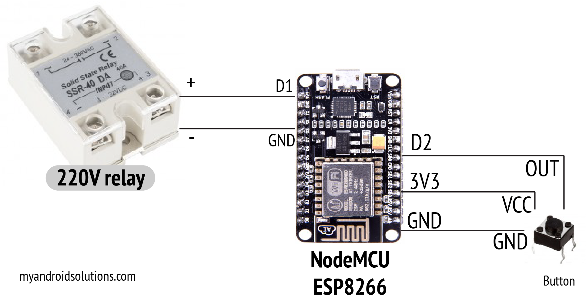
Note that the wiring diagram does not position the lines to the real GPIO pins, instead I noted the exact GPIO pins so the position will be different than in the diagram. D1 corresponds to GPIO5, D2 to GPIO4 so in the Arduino code you will find them referenced as 5 and 4. Also, the relay I am using emits a charge of a few volts back to the board. That makes the button press detection to trigger false positives. There is a way to outcome that hardware wise but I don’t know exactly the component that I should use in order to avoid the charge and so I made some hacks in the Arduino code. I will get back with updates when I will find out how to fix it properly. If you know how, please let me know.
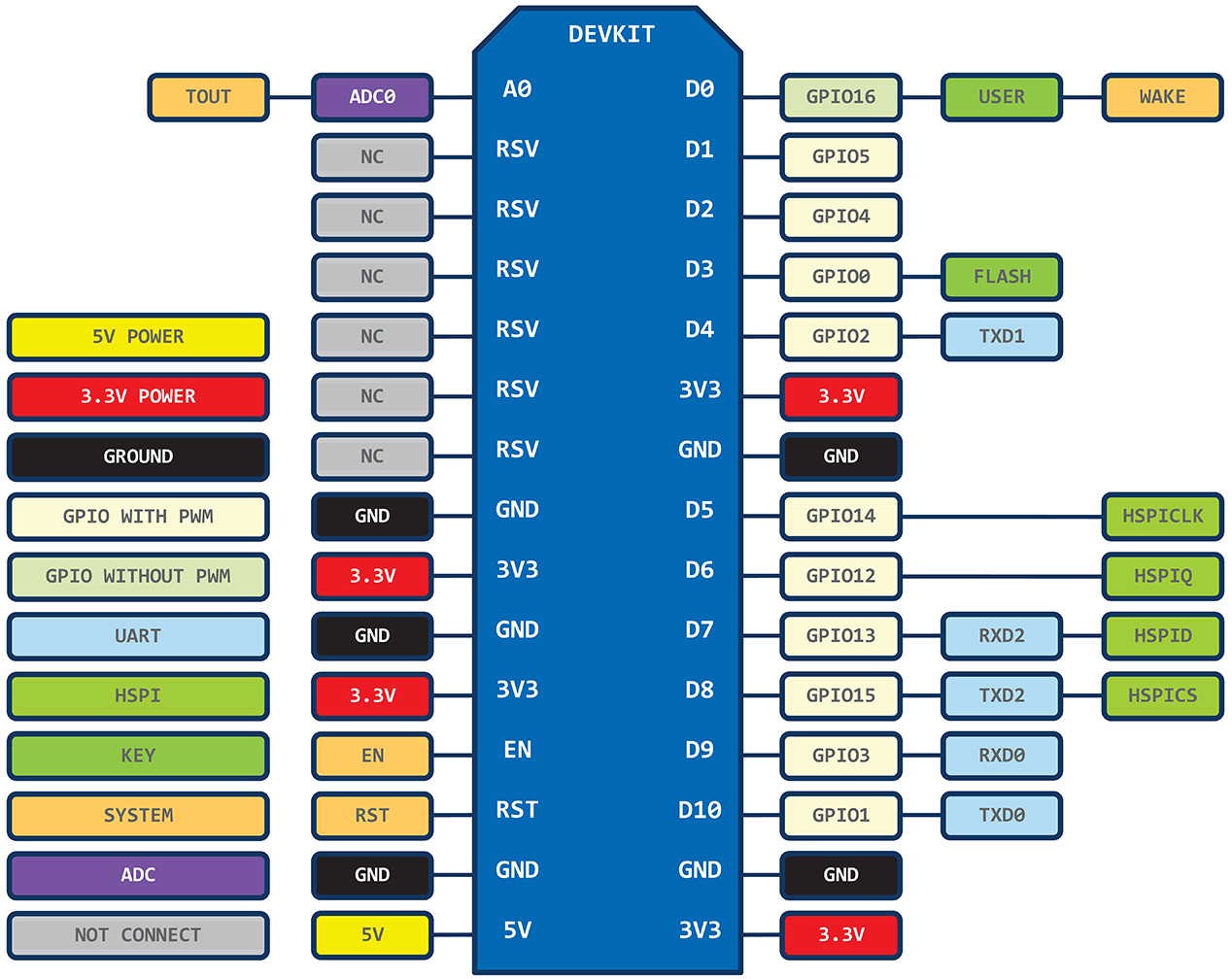
Below you can find the NodeMCU ESP8266 pins layout. You can find out more about that here.
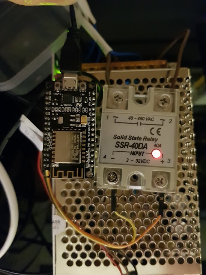
Below you can also see a small sample of how my setup looks like (I know, it doesn’t look nice, I bought some stuff to box it :) ).
A few details…
The led band is powered by a transformer that outputs 24V from 220VAC. What I’ve done was to put the relay in front of the 220VAC of the source and switch it off and on whenever I need it to. The ESP8266 sends a 3VDC power to the relay and in that moment the relay turns ON and the led band lights up.
I bought a solid state relay because those are responding faster and have longer life than the other one. Please share your thoughts if this doesn’t make sense for you. The whole project(hardware) cost me about 40 dollars (max) and it is not built with cheap components so one could get it below that(depending on the region and trading skills :)) ).
The code for both the Arduino and Android projects can be found on my Github account HERE. Please let me know if you have issues or you have better ideas and feel free to contribute.
At last
I would like to end with a list of items that I want to address in the future and also some util links.
Future improvements:
- fix the relay leak hardware wise and not in code
- implement a well known and widely used IoT things protocol so that other smart home servers could talk with my “smart relay”
- implement a better wifi connection and discovery mechanism (remember the connection after a restart…)
- refactor the android app to abstract the “Thing” and add support for future things
- integrate with IFTTT
- integrate with Google Assistant
Util links:
- KazyHome Github repository
- Arduino language reference
- NodeMCU documentation
- ESP8266 Github repository
Thank you for reading all this long post, please let me know if you managed to setup this and also your opinion/experience with IoT.
Meanwhile I managed to link the ESP8266 to my Google Home assistant speaker using IFTTT using a web hook for now. See the video below.
And a short demo with the beast :)